How to Use Automotive Multimeter: Step-by-Step Shop Guide
How to use an automotive multimeter for car diagnosis: dial settings, lead placement, DC voltage checks, continuity inspection and safe parasitic draw measurement.


On this page
Top picks at a glance
As an Amazon Associate we earn from qualifying purchases.
- 1
 Fluke 88V Deluxe Automotive Multimeter9.6/10View on Amazon
- 2
 INNOVA 3320 Auto-Ranging Digital Multimeter9.6/10View on Amazon
- 3
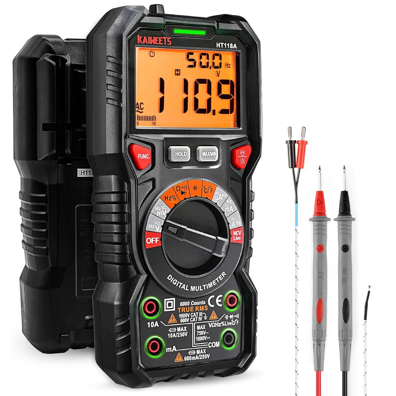 KAIWEETS Digital Multimeter Automotive TRMS Tester 60009.6/10View on Amazon
- 4
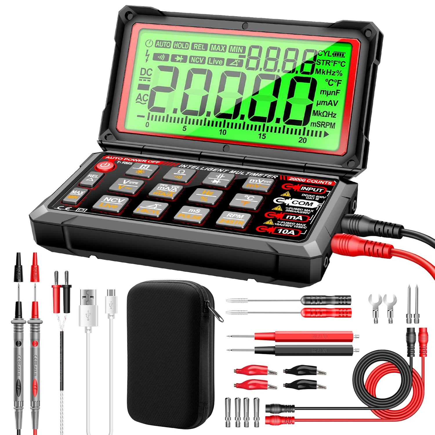 ANENG 20000 Count Digital MultimeterView on Amazon
- 5
 AstroAI Digital MultimeterView on Amazon
- 6
 Innova 3340 Professional Automotive Digital MultimeterView on Amazon
- 7
 GEARWRENCH Automotive Pro Digital MultimeterView on Amazon
- 8
 ANENG 0.5V-600V MultimeterView on Amazon
When an engine refuses to crank or a starter clicks without turning over, knowing how to use automotive multimeter settings lets you diagnose vehicle electrical problems without guessing. To use an automotive multimeter, connect the black probe to the common COM port and the red probe to the voltage terminal, set the dial to DC voltage, and touch the probe tips across the battery posts or circuit points to measure electrical potential. From there, switch between DC voltage for charging checks, resistance on unpowered components, and series current for parasitic drains step by step.
More options to compare
 ANENG 20000 Count Digital MultimeterCheck price on Amazon
 AstroAI Digital MultimeterCheck price on Amazon
 Innova 3340 Professional Automotive Digital MultimeterCheck price on Amazon
 GEARWRENCH Automotive Pro Digital MultimeterCheck price on Amazon
 ANENG 0.5V-600V MultimeterCheck price on Amazon
GarageToolHQ earns a commission when you buy through links on our product pages, at no extra cost to you. Read our affiliate disclosure.
Below: lead jack connections and rotary dial settings, primary diagnostic modes for vehicle circuits, and a step-by-step checklist to inspect electrical components safely.
How to use automotive multimeter settings: where electrical risk comes from
Passenger vehicles run on direct current, but improper meter connections create immediate hazards for vehicle electronics and the meter itself. Multimeter mistakes create several distinct garage risks:
- Blown meter fuses from improper current checks. The amperage jack routes through a low-resistance shunt to common. Touching leads across a voltage source while in an amperage jack surges current through the shunt, blowing the fuse. Fuses also blow if series current exceeds the meter’s rating.
- Circuit damage during resistance checks. Resistance mode sends internal sensing current through the probes. Probing energized circuits backfeeds vehicle voltage into internal meter circuits. Conversely, sending sensing current into sensitive solid-state electronics or airbag circuits can damage modules or deploy restraints.
- Accidental short circuits across harness pins. Probing tightly spaced connector pins with bulky probes can bridge adjacent terminals, causing sparks, blown fuses, or module damage.
- Transient spikes from inductive components. Ignition coils, relays, and alternators create steep voltage spikes when magnetic fields collapse, requiring adequate surge suppression ratings.
Primary automotive multimeter settings, and how they apply to car circuits
| Setting | What it measures | Automotive application |
|---|---|---|
| DC Voltage (V with straight line and dashed line) | Electrical potential difference between two points in an open or closed circuit | Battery resting state, alternator charging output, sensor supply references, and circuit voltage drop across cables |
| Resistance and Continuity (Ω and audible beeper) | Opposition to electrical flow or unbroken circuit paths without vehicle power | Blown fuse checks, harness wire continuity, relay coil integrity, switch contact operation, and clean chassis ground bonds |
| DC Current (A and mA with DC symbol) | Flow rate of electrons through a complete circuit path in series | Tracking parasitic battery drain across fuse panels with the vehicle in sleep mode |
| Automotive Specialty Functions (RPM, dwell, duty cycle) | Engine rotational speed, ignition contact duration, and pulse width modulation | Fuel injector opening duration, idle air control duty cycle, and engine tachometer calibration |
Input jacks and dial positions determine whether the tool measures properly or damages a fuse. For advanced diagnostics, Fluke lists millisecond pulse width measurements for fuel injectors on the Fluke 88 V/A combo kit, with Category III to 1000V and Category IV to 600V safety ratings. For engine analysis, ANENG lists engine speed measurements from 300 to 19,999 RPM on 2 or 4 cylinder engines, dwell angle across 1 to 8 cylinders with 0.1 degree resolution, and pulse width up to 999.9ms on the 20,000 count ANENG 623. General meters also vary: Fluke lists voltage up to 1000V, current to 10A, and resistance to 40 MΩ on the Fluke 17B+ and Fluke 15B+, while KAIWEETS lists an IEC Rated CAT III 600V rating on the KM100.
How to use automotive multimeter checks safely: the step-by-step checklist
- Plug the black probe into the common port. Connect the black probe to COM, which serves as the reference ground for all measurements.
- Insert the red probe into the voltage port. For voltage, resistance, and continuity, insert the red probe into the V-Ω port. Leave amperage jacks empty until measuring current.
- Set the selector dial to DC voltage. Select DC voltage (V with straight and dashed lines) for standard circuits. Reserve AC voltage for specialized checks, like inspecting alternator rectifier diodes for ripple voltage.
- Verify resting battery voltage across posts. Touch the red probe to positive and black to negative with the engine off to read open-circuit potential against manual specifications.
- Observe cranking voltage during start. Keep probes on the battery while cranking. If voltage collapses excessively, the battery or starter motor requires attention.
- Verify alternator charging voltage at idle. With the engine idling, voltage across the battery should rise above resting state as the alternator charges.
- Perform voltage drop checks under load. Keep the circuit operational and measure voltage across power cables or between component grounds and the negative battery post to reveal hidden resistance.
- Isolate and de-energize circuits for resistance checks. Disconnect power and remove fuses from sockets before checking ohms or continuity to prevent backfeed errors.
- Turn the meter off and stow probes. Switch the dial to OFF to save battery power, and return probes to protective holders.
Applying probes set to ohms or continuity to a live automotive wire can send external vehicle current directly into the internal meter components. Always disconnect the battery ground cable or unplug the component connector before checking resistance.
Use rated jack stands on solid ground, wear eye protection with power and air tools, keep fuel-burning equipment out of a closed garage, and follow the manual for every tool. Read our Safety Disclaimer.
Automotive multimeter vs OBD2 diagnostic scanner
Modern vehicles contain complex electronic control networks, making it helpful to understand how an automotive multimeter differs from an OBD2 scan tool:
- Measurement method: A multimeter checks voltage, resistance, and amperage directly at conductors. A scan tool reads digital trouble codes and live sensor data from vehicle computers.
- Troubleshooting role: A scan tool flags abnormal circuits; a multimeter verifies whether wiring delivers clean power, ground, and signal integrity to the sensor.
- Direct circuit verification: A multimeter evaluates physical circuits independently, checking power feeds, relays, and grounds regardless of computer reporting.
- Component isolation: When a trouble code flags a sensor, a multimeter confirms whether the part is defective or suffering from a loose wire before replacing it.
If you want to read computer trouble codes or monitor live engine data streams, explore our guide on how to choose an OBD2 scanner, or see our top recommendations in the best OBD2 scanner for DIY guide. To understand diagnostic code structures before troubleshooting, read our overview on what do OBD2 codes mean. When selecting a dedicated meter for garage diagnostics, compare our top picks in the best automotive multimeter roundup.
Current measurement and meter fuse protection
Measuring direct current isolates parasitic battery drain that flattens a battery overnight, but improper connections easily damage the tool.
Current flows through an internal low-resistance shunt. Touching probes across a battery while in an amperage jack dead-shorts the terminals. Multimeters include internal fuses to protect circuits against over-current damage. For example, KAIWEETS lists an IEC Rated CAT III 600V safety rating with anti-burn double fuses on the KM100, and includes cable leads measuring 48 inches. Klein Tools lists a 10A current limit on the MM420 and MM460S, resistance up to 50MΩ, and drop protection rated for a 6.6-Foot (2 m) fall, while Fluke provides 10A current input protection and CAT III 600V ratings on the Fluke 17B+ and Fluke 15B+.
To measure parasitic draw, disconnect the negative battery cable with the ignition off and connect the meter in series between the cable clamp and battery post with the red lead in the high-current jack. To maintain batteries during storage or diagnosis, connect a smart battery charger maintainer, or view our top picks for the best car battery charger.
Frequently Asked Questions
Which jack should the red multimeter lead plug into?
The black lead connects to COM. The red lead plugs into the V-Ω port for voltage, resistance, and continuity. Only move the red lead to an amperage jack for in-series current checks, and return it to the voltage port immediately after.
Can checking vehicle voltage blow my multimeter fuse?
No. In voltage mode, the meter presents high internal impedance, drawing negligible current. A fuse blows only if the red lead is plugged into an amperage jack across voltage, or if series current exceeds the fuse rating.
Why must a circuit be unpowered before checking resistance?
Resistance modes send sensing current from the meter battery through the component. Outside voltage from a live circuit interferes with readings and damages internal meter circuits.
What is the difference between auto-ranging and manual ranging?
Manual ranging requires choosing the measurement bracket on the dial beforehand. Auto-ranging senses signal strength automatically and selects the scale with optimal resolution.
Can an automotive multimeter measure engine speed and fuel injector signals?
General multimeters read basic electrical properties, often adding frequency or temperature. Dedicated automotive meters add engine diagnostic modes. For instance, ANENG lists engine speed from 300 to 19,999 RPM on 2 or 4 cylinder engines and dwell angle for 1 to 8 cylinders on the 20,000 count ANENG 623, while Fluke lists millisecond pulse width measurements for fuel injectors on the Fluke 88 V/A kit.
Why does the multimeter display show OL during a continuity check?
OL means Open Loop or Over Limit. On continuity or resistance, OL indicates infinite resistance from a broken wire, open switch, or blown fuse.
Related: best automotive multimeter, our diagnostics and electrical hub and best OBD2 scanner for DIY. Also see our guides on how to choose an OBD2 scanner and best car battery charger.